
August was an incredible month for accomplishments.
Wings Removed and Fuselages/Center Section Pivoted
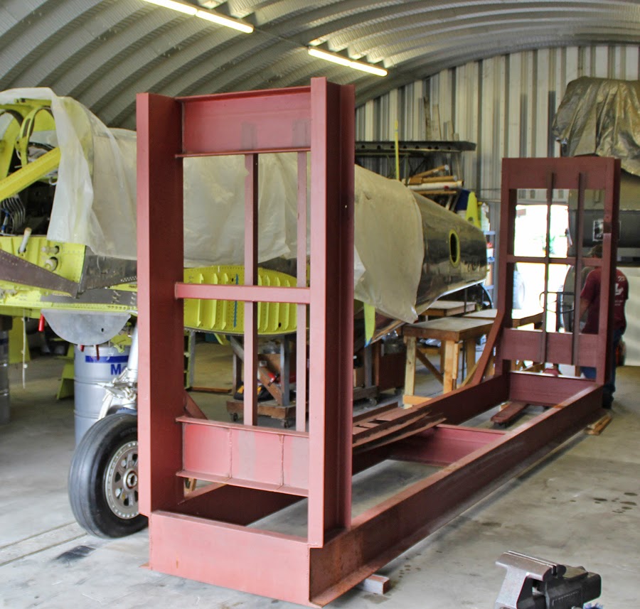
This past 15 August the time came to turn the fuselages/center section 90 degrees to the south in our hangar. We used the factory-mounted 45 degree lift points on the inboard side of the center section, right against the fuselage lower longerons. These lift points (¾-16 threaded ports) are designed to bear the entire weight of the aircraft including the engines. We were able to lift the entire balanced center section with both fuselages and engine mounts with one man lifting and guiding each rear fuselage. The lift and pivot took only about two hours to reposition the aircraft where it would fit out the large south door.
After the lift and pivot, we leveled the aircraft in pitch and roll to within 1/30th of one degree, about the thickness of a piece of cellophane. We manufactured two vertical steel support pipes to fit into the rear jack points (right forward of the tail wheel attach), and designed them to be vertically adjustable. At that time we leveled both fuselages on the center section by using the factory shims, and are final-attaching the fuselages to the center section longerons with the remaining six of the twenty internal wrenching NASA bolts. (Longerons are the main beams that are the lower structural rails mounted in the bottom of both fuselages.)

We moved the outboard wing fixture into the hangar and attached the wings to check the washout and made the final microscopic adjustments.
Verticals, Horizontal and Rear Fuselage Extensions
The next day we installed all of trim actuators in each vertical and the horizontal, (three) and installed all the trim cable pulleys in each vertical.


We then attached each vertical to its respective side of the horizontal stabilizer. We had to align and hold the verticals in a perfect 90 degree position in relation to the horizontal stabilizer. We used diagonal wires and turnbuckles to make the final tiny adjustments as the verticals are permanently held in place when the aft fuselages are high-shear riveted and bolted to the forward fuselages.
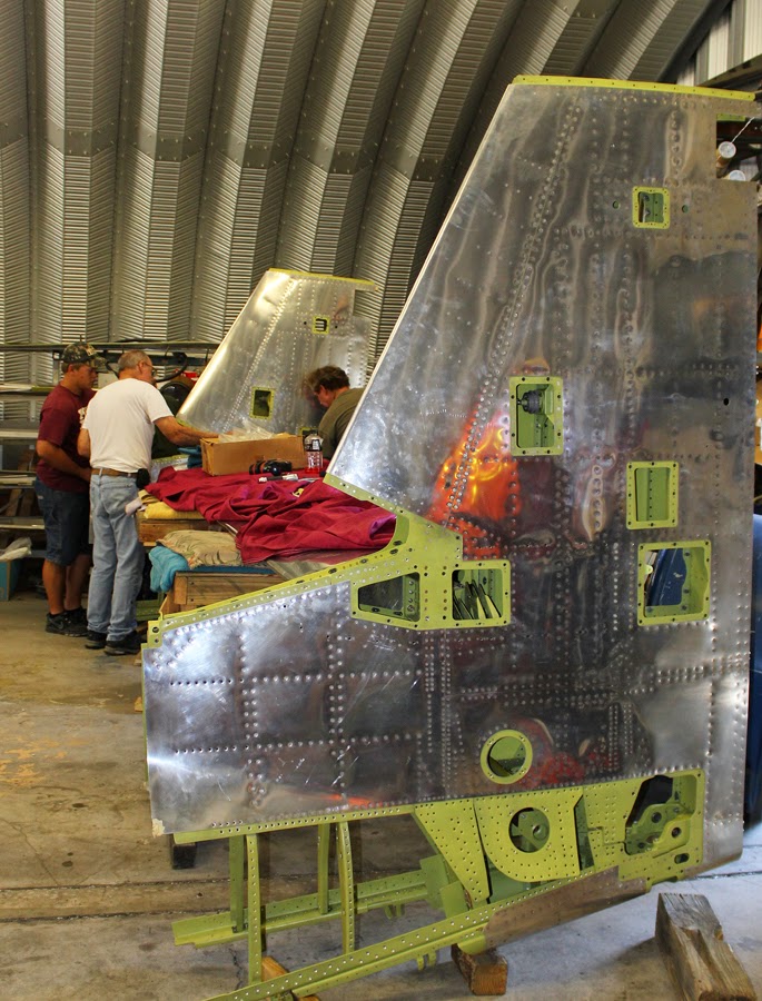

The following Saturday the team built a temporary cushioned wood scaffold and lifted the horizontal/verticals/aft fuselage sections up and forward to within ½ inch of their final attach positions.

Then came all of the final adjustments to make sure everything was properly aligned prior to drilling and reaming any of the attach holes for the fittings. There were eight exact measurements that had to be aligned:
* The angle of incidence (the pitch up and down on the horizontal stabilizer in relation to the center section.
* The alignment of the two vertical stabilizers (toe in, toe out).
* The exact vertical measurements on the verticals in relation to the horizontal measured between the two top and two bottom rudder hinge points horizontally and diagonally.
* The exact forward and aft dimension of the center section trailing edge to the leading edge of the horizontal stabilizer.
* The left and right measurements on the aft fuselage extensions to the forward fuselages. This exact measurement is obtained by shaving the attach fittings of the horizontal stabilizer to the vertical stabilizer. We intentionally machined all four of them 1/32" thicker to give us extra material if we needed to make small adjustments.
* The twist of both aft fuselage extensions to align the upper and lower attach points.
* The vertical attachment of the aft fuselage extensions to the forward fuselage attach points.
* The alignment of the dorsal fins with the leading edge of the vertical stabilizers.
Everything lined up perfectly. So then the team started final drilling and reaming all the attachment hardware for the high shear rivets.
Outboard Wings and Center Section
We completed the riveting of all the top skins while on the fixture, and one more bottom skin on each wing which locked the wings into their final shape.
Both wings are now off the fixture, and the team is completing the final riveting and finishing the fuel cell stand-off angles.
Two of our team members are now fitting and installing the new aileron attach hinge point fittings. One of our machine shops is making the final two outboard flap hinges.


The new inner and center aileron attach hinge point fittings
are now being installed on both wings.

Two inboard and two outboard ailerons
The final Adel clamping of the wiring harnesses in the center section is now being completed along with the final attachment of the three wiring terminal strips in each wheel well. One of our volunteers is sewing the canvas covers that shield and protect these wiring bundles and terminal strips from dirt and moisture thrown up by the rotating tires on retraction. Thank you.
The center section nut-plate channels, that attach the fuel tank close-out panels between the outboard wing and center section, are now completed.

Fuel cell stand-off angle installed.

Newly machined forward and aft door lock bell crank
mounts for each main gear door

The new wheels and tires are now installed on the main gear legs
The Katz
"You will not get into this rivet case until I get my treats!" --- Allison

Thankx
Tom
Thanks for another amazing update. Your detailed description of work performed enables this outsider to appreciate the care and craftsmanship required to do a job of this scope and scale. Best of luck in all future tasks!
ReplyDeleteI would love to see the outboard wings in the fixture, to gain an understanding of the measurements and final adjustments. Is this possible?
ReplyDeleteWeezie, our photographer, driller, plans guru and everything else in our shop, was out of town for a week visiting family. Pictures of wings in the fixture didn't happen. You can check the washout on two known points on the wing chord line at the root end, and the same known chord points on the tip end. You compare the difference and it gives you the washout (twist). The chord is an imaginary straight line, location determined by the factory from the leading edge to the trailing edge of the wing.
ReplyDeleteCool. Thanks.
Delete